
Project Sponsor: Amarillo National Bank ($30,000)
Collaboration with Lenora Ask, AIA
Research Assistant: Zoe Wall
Fabrication Assistants: Alexis Martinez, Abigail Petrofes, Enrique Espinoza, Demarcus Clarke
Firing Assistance: Von Venhuizen
ABSTRACT: This project presents the "Shift," a research initiative exploring the application of clay 3D printing (C3DP) in full-scale architectural design. The project involved the design and construction of a wall composed of 320 clay blocks, each featuring a shifted sinusoidal geometry generated using computational design tools. The design enhances aesthetic appeal and redirects winds for better environmental performance. “Shift” addresses the growing need for sustainable construction methods by utilizing clay, a low-carbon and recyclable material, and minimizing material waste through additive manufacturing.
Key aspects of the project include:
Exploration of C3DP capabilities for creating complex architectural forms that are difficult to achieve with traditional methods.
Assessment of environmental benefits, including the use of a renewable material, reduction in material waste, and potential for performance-based designs.
Interdisciplinary collaboration among architects, computational designers, ceramicists, and masons to overcome technical challenges.
Development of a technical framework for integrating C3DP into architectural design and construction processes.
The design process involved adapting a shifted sinusoidal tile concept to a masonry wall, optimizing block size, layer height, and material selection. The fabrication process utilized a fused deposition modeling technique with a 3D PotterBot 10 PRO printer and employed a circular method of recycling unfired clay to reduce manufacturing waste, further promoting sustainability.
The project successfully demonstrated the feasibility of C3DP for creating functional and visually striking architectural elements while effectively screening mechanical units. The wall's interaction with the local climate, including the capturing of prevailing winds, has not been measured, though this was a design intent. The "Shift" project contributes to the growing body of knowledge in sustainable construction by showcasing the potential of C3DP, and it sets a benchmark for future endeavors that blend aesthetic innovation with ecological responsibility.
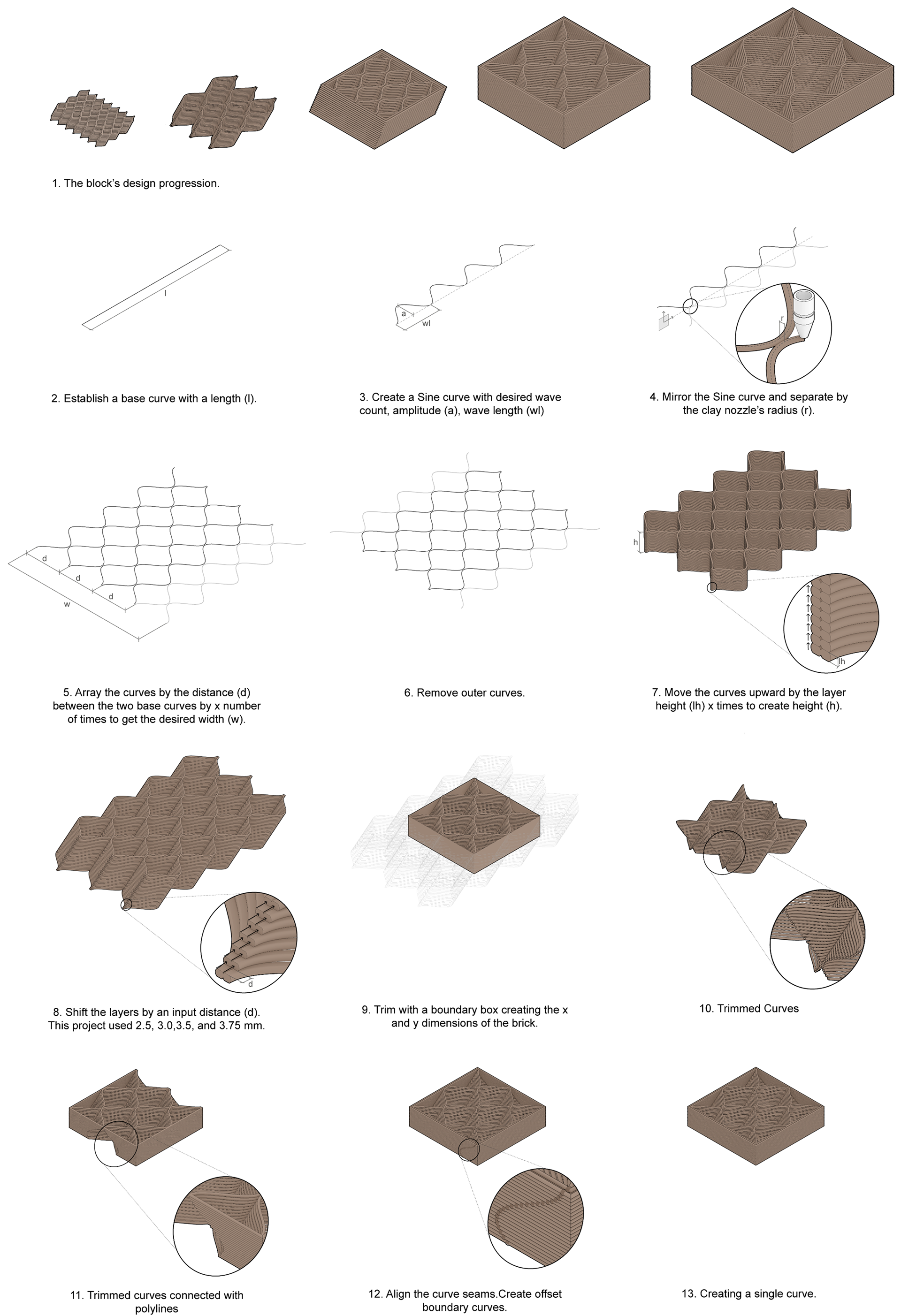
Diagram detailing the block's design process and computational logic diagram.
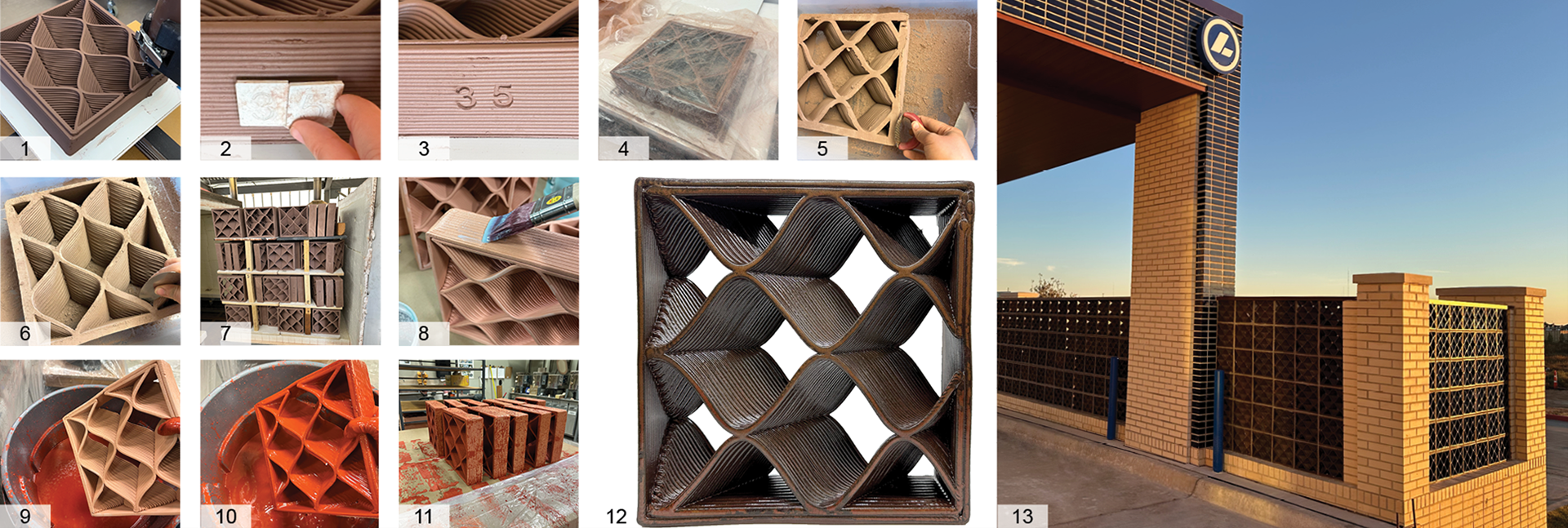
1. 3D printing a block 2. Stamping the shift distance into block 3. The resulting stamp 4. Wrapping the block in plastic wrap 5. Using a rasp tool for sanding 6. Trimming the bottom layer 7. Loading the kiln for bisque firing 8. Applying wax resist 9. Preparing to dip the block in glaze 10. Block dipped in glaze 11. Blocks drying 12. Completed block 13. Blocks installed on-site.
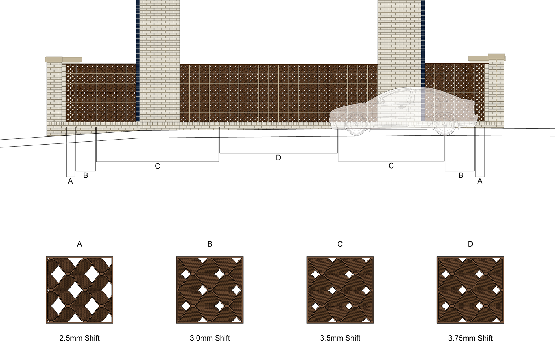
This diagram shows where the cars go through the drive-through; therefore, blocks were used to obstruct the view of the mechanical systems. A gradient of blocks was used. Block designs C and D were used where the cars would spend the most time, so the views were the most obstructed.
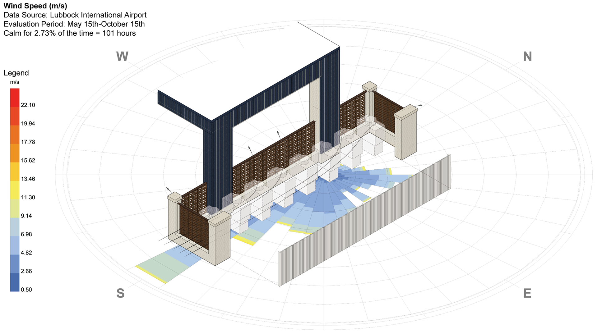
Isometric illustration of the constructed block walls in relation to the prevailing wind directions.