
Collaboration with Yaxuan Liu
Professors: Sawako Kaijima
Harvard Graduate School of Design | Fall 2020
ABSTRACT
Our project NuBlock brings a modern and aesthetic update to an architectural and structural elementary unit—brick. With its innovative water-soluble formwork, this project can create lighter concrete bricks through a gradient of variable porosities with intricate geometries and infinite customizability. Thanks to its customizability, NuBlock’s porosity can directly relate to its location’s structural need. In areas where greater structural stiffness is required the block is denser and vice versa. The goal is to minimize the quantity of material necessary through formal optimization while maintaining its structural performance and decreasing the embodied carbon latent in concrete fabrication.
BLOCK DESIGN, MAPPING + CASE STUDIES
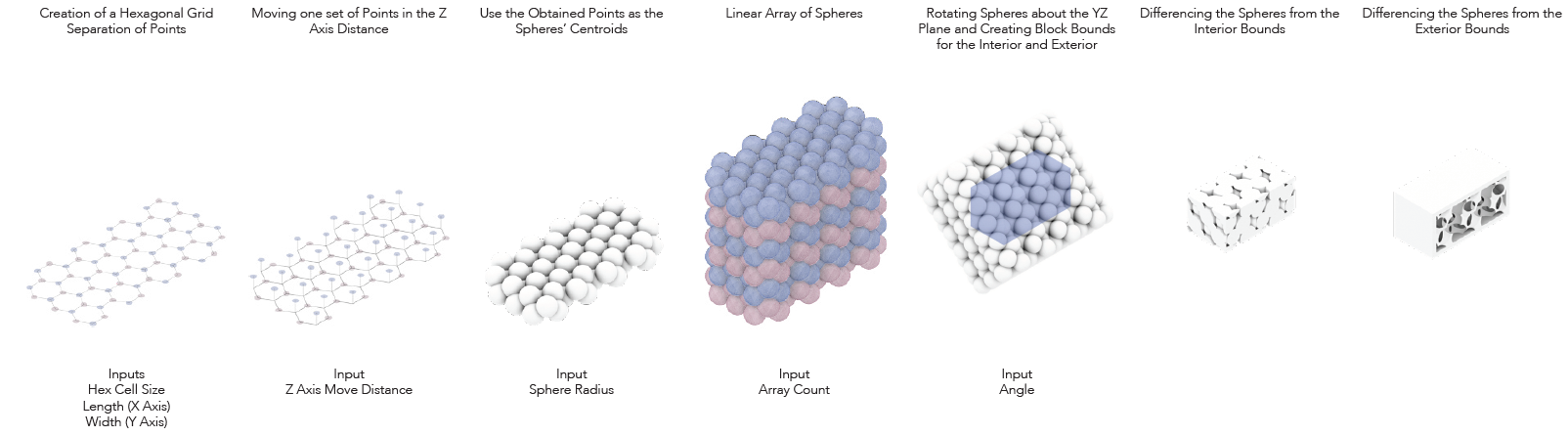
The brick was based off hexagonal sphere packing. The cell size determined the density of the spheres which allowed for varying porosities. The angle of the sphere array can be changed to allow for varying direction of porosity that can augment the view or the lighting. The spheres were used to remove material from a block. An exterior boundary remained on four sides to make the module more legible once populated on a structure.
Two case studies were investigated using very different structures to showcase NuBlock’s versatility. These two studies were a staircase core and a shell structure.
Polyvinyl Alcohol (PVA) is a biodegradable, water-soluble polymer that is used in 3D printing as a support structure for a second 3D print material. When exposed to water it will dissolve. This material is what is used to hold the detergent in pods and are the composition of glue sticks.
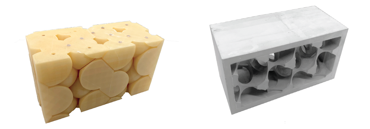
For this project PVA was used as a primary print material for use as concrete formwork. As formwork, it has allowed for the creation of concrete components with hollow parts, undercuts, as well as other scenarios in which removing or breaking the formwork would be impossible without breaking the cast. Typically, casting complex forms in concrete requires large and multipart formwork but, with PVA, a single mold can be used as shown in the diagram on this slide. The PVA formwork at left would dissolve leaving the intricate block at right.

Ten brick types were designed with a gradient porosity. The depth of the bricks range from eight to twelve centimeters from the most porous to the least porous.

A corner block was designed to aid in turning the corner without losing porosity.
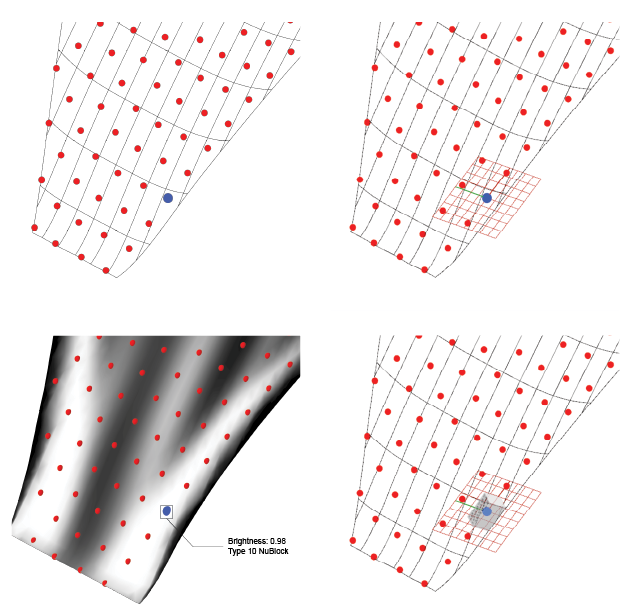
In order to map NuBlocks according to the stiffness map from finite element analysis and optimization, a grid was populated onto the surface and used to sample the UV tangents (and/or contour line tangents), and stiffness map brightness, which are used to determine the block orientation and type. The selected bricks are mapped onto the surface so that their centroids are at the corresponding grid points.
STAIR CASE CORE CASE STUDY
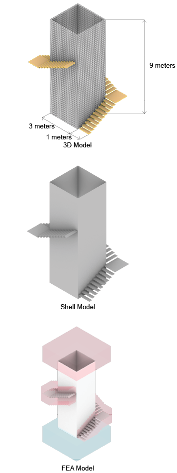
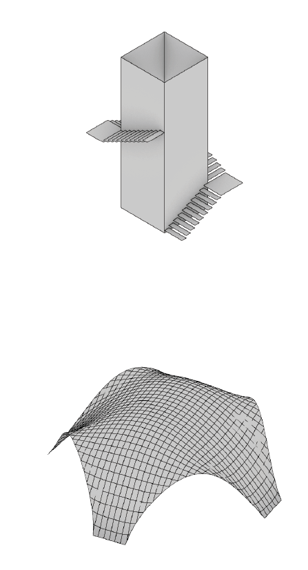
The staircase core case study started with a finite element analysis in Millipede, a plugin for McNeel’s Grasshopper, of the structure. The 3D model at left was translated into a shell model to be analyzed and optimized. The staircase wraps about the three-by-three-meter masonry core which is nine meters tall. The model on the right shows the model that was input into Millipede. The structural load is represented in pink. The stair is loaded with five-thousand newtons per square meter with a safety factor of three while the roof load is two-thousand newtons per square meter and a safety factor of five. The blue denotes the support structure.
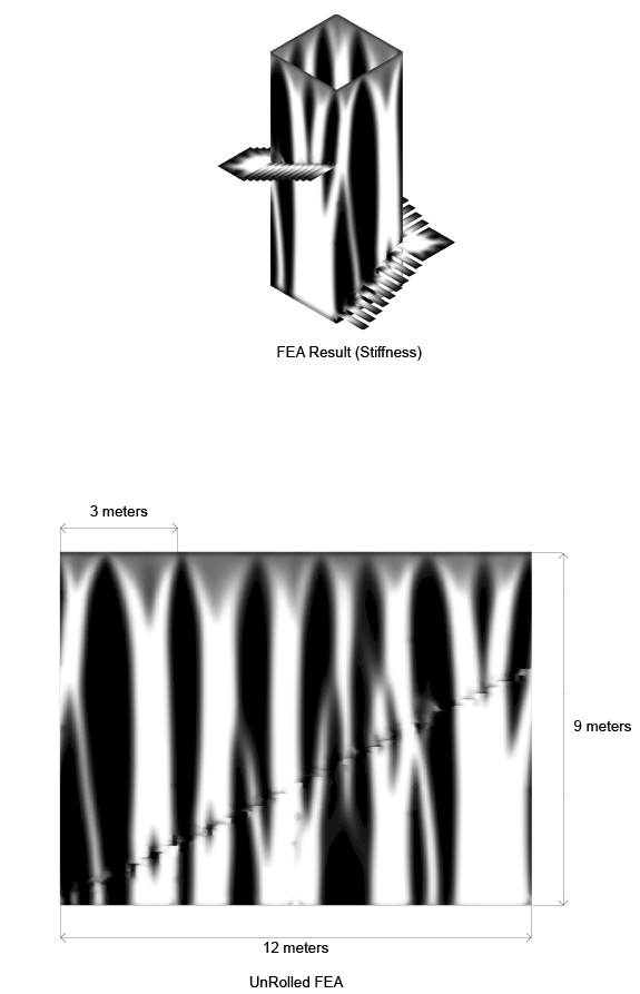
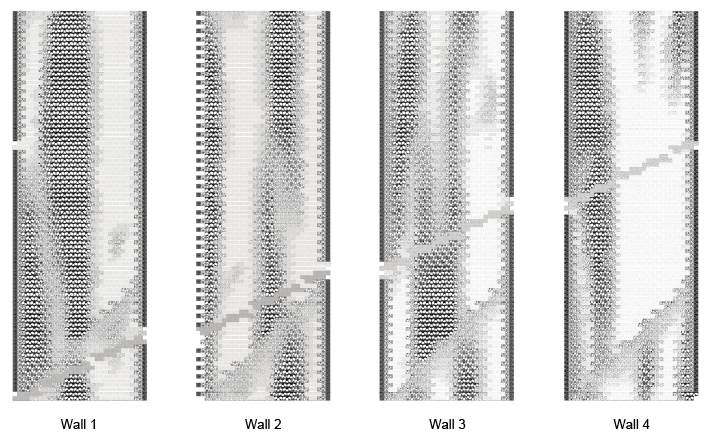
The diagrams at right denote the stiffness map from the FEA optimization. The white areas are where the most structural stiffness is desired while the least is required in the black areas. The rightmost diagram is an unrolled stiffness map of the three-by-three-meter masonry core.
The renders at right show the blocks mapped onto the structure according to the FEA optimization result. Solid blocks were placed in areas where the floating stair is mounted.
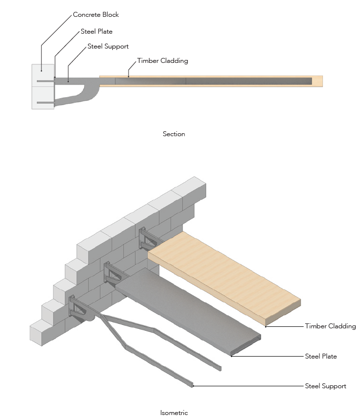
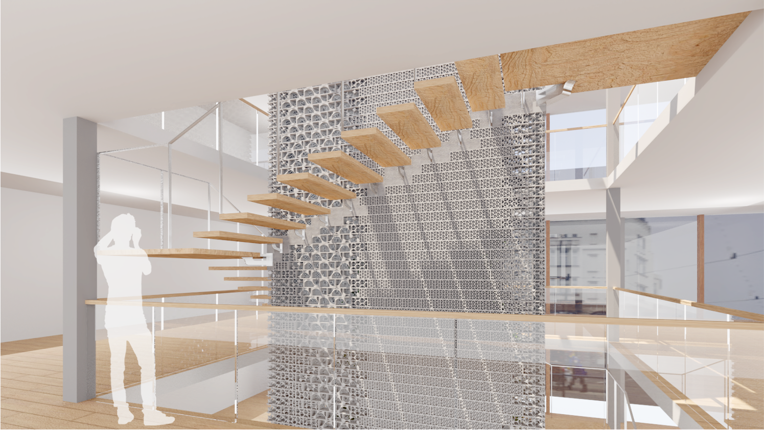
A stair was designed to be subtle and complement the block, with the intention of not taking away focus from the porous concrete blocks. The stair’s steel support assembly was designed using Finite Element Analysis. This analysis allowed for the development of a rectangular extrusion steel support. This support would be cast into the concrete blocks. The steel support would be clad with a steel plate and timber.
The corner landing follows the same structural and material logic as the standard treads.
Close-up Speculative Rendering
View at the Staircase Base
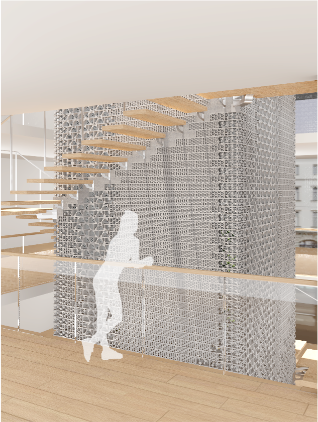
View at the Second Floor
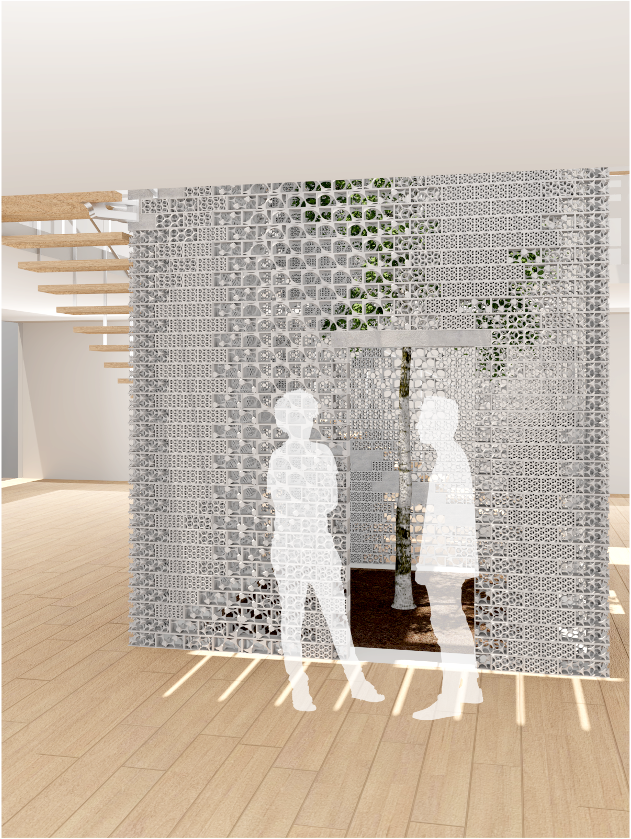
Blocks can be removed in areas where the blocks are most porous to allow for openings
Another View from the Second Level
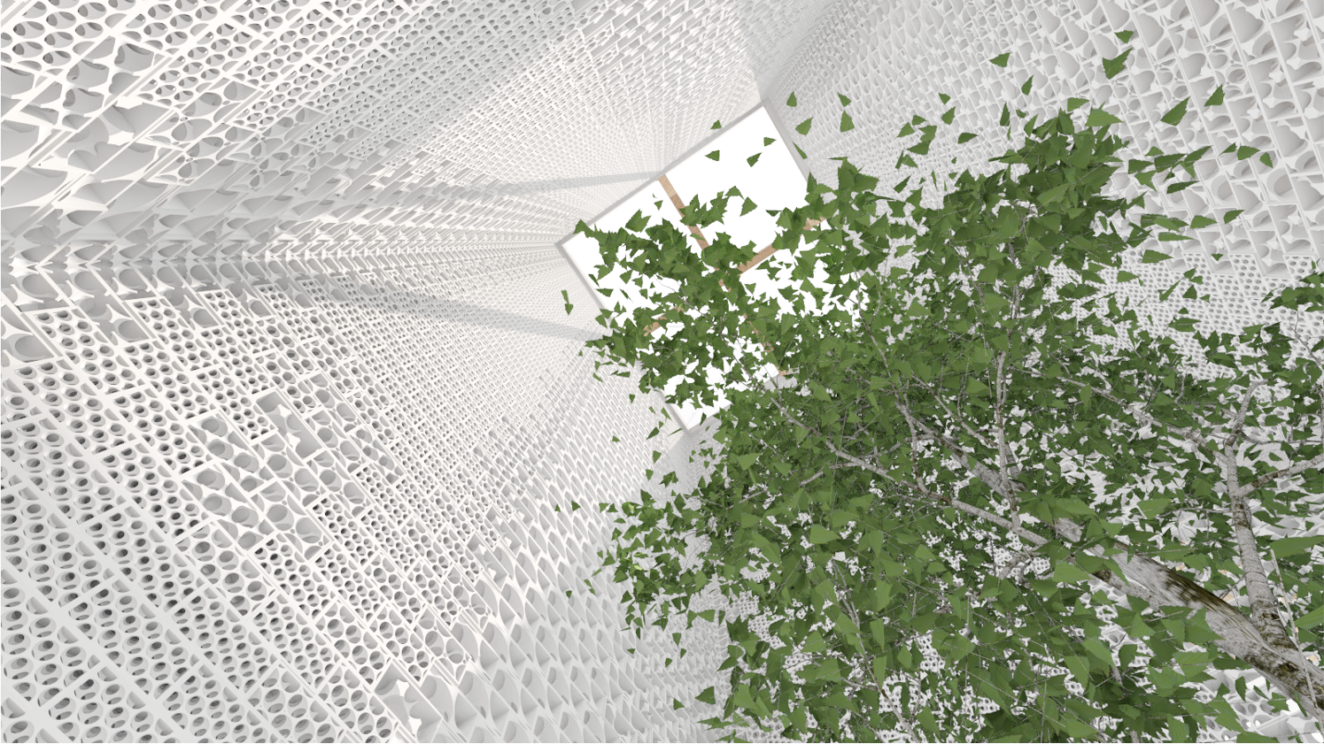
View Looking Upward from the Courtyard
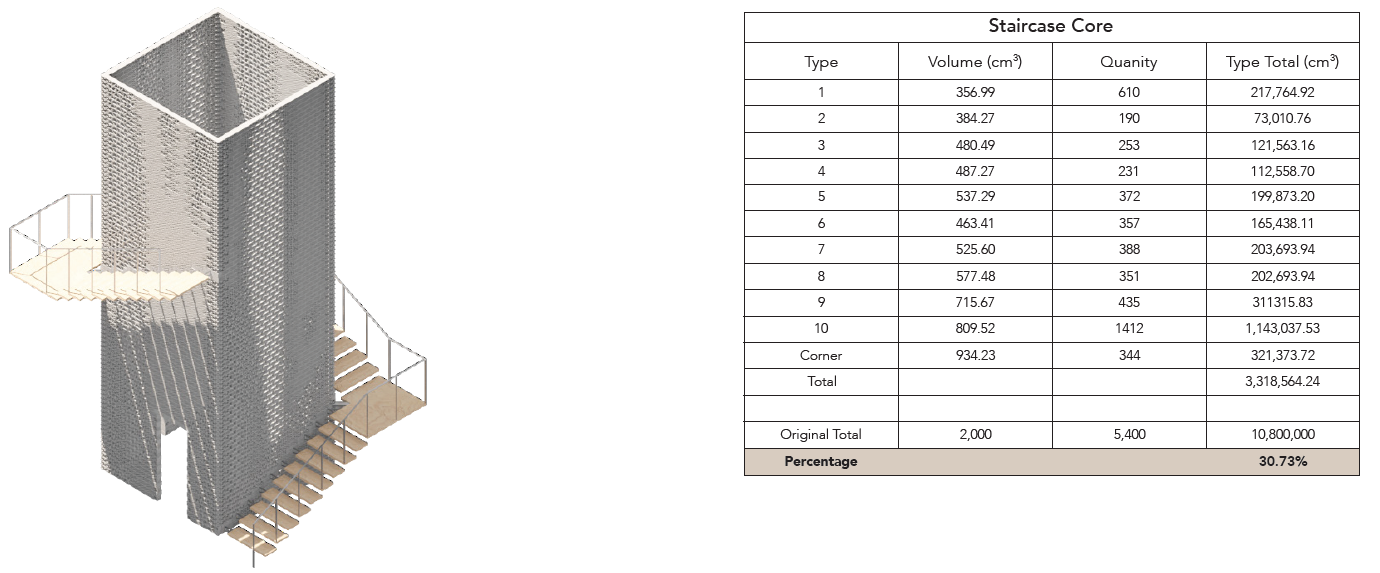
The structure was only 30.73% the volume of this structure with traditional blocks.
SHELL CASE STUDY
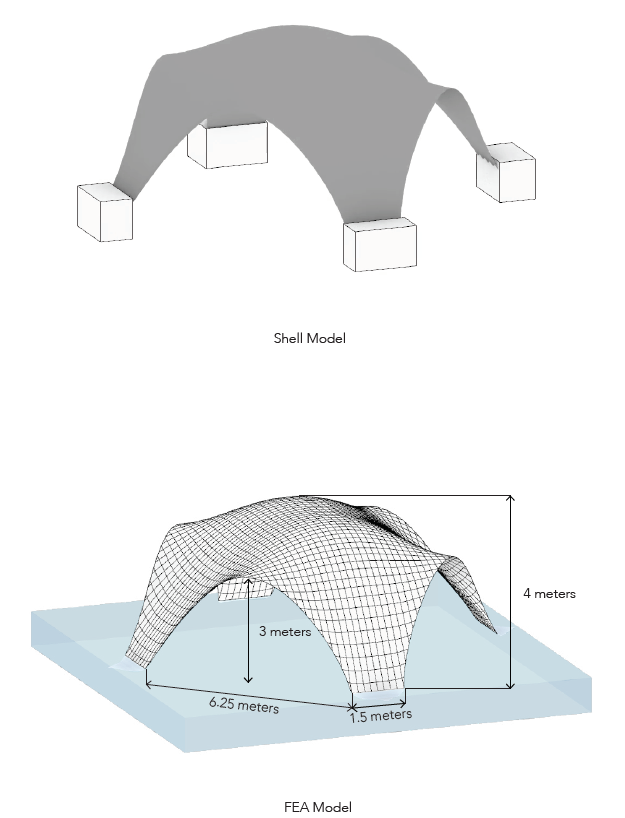
The shell model analyzed and optimized a Catalan vault with its self-weight. The geometry was generated through the draping of a chamfered square which created the most efficient structure. Each anchor is one and one-half meter in length. The openings are six and one-quarter meters wide and three meters tall. The structures height is four meters.
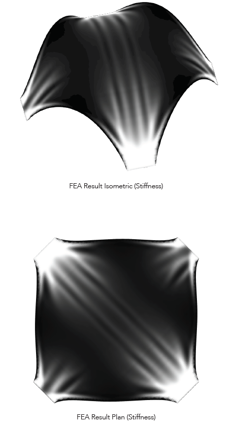
The diagrams at above denotes the stiffness map from the FEA optimization. The white areas are where the most structural stiffness is desired while the least is required in the black areas.
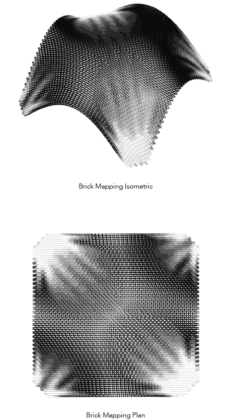
After trying a variety of different patterns of packing, this one was chosen as it highlights the geometry the best and approximates the stiffness map well.
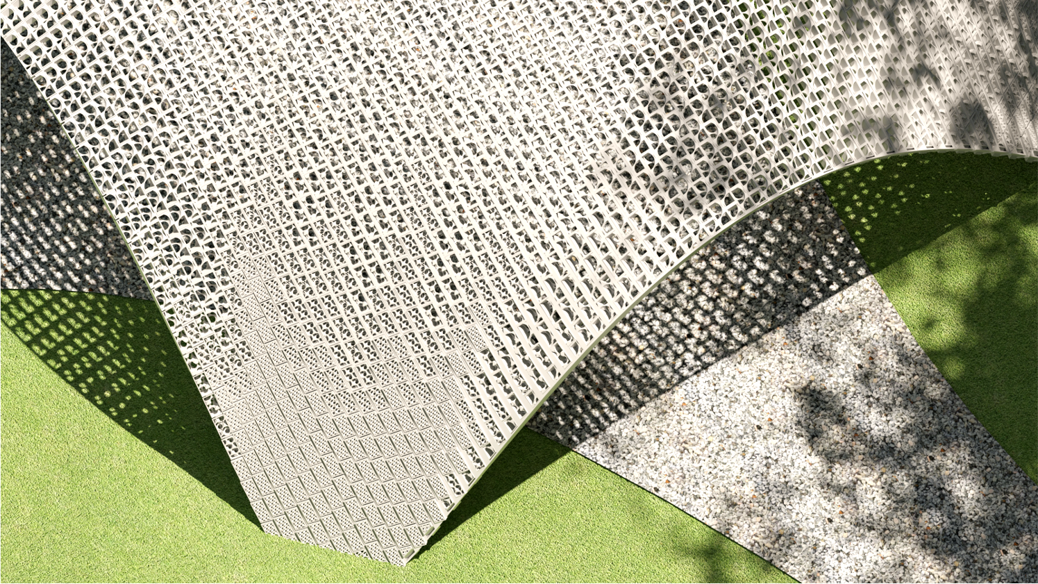
Close-up render of the mapped blocks. The structure is denser closer to the support and becomes more porous as it approaches the center.
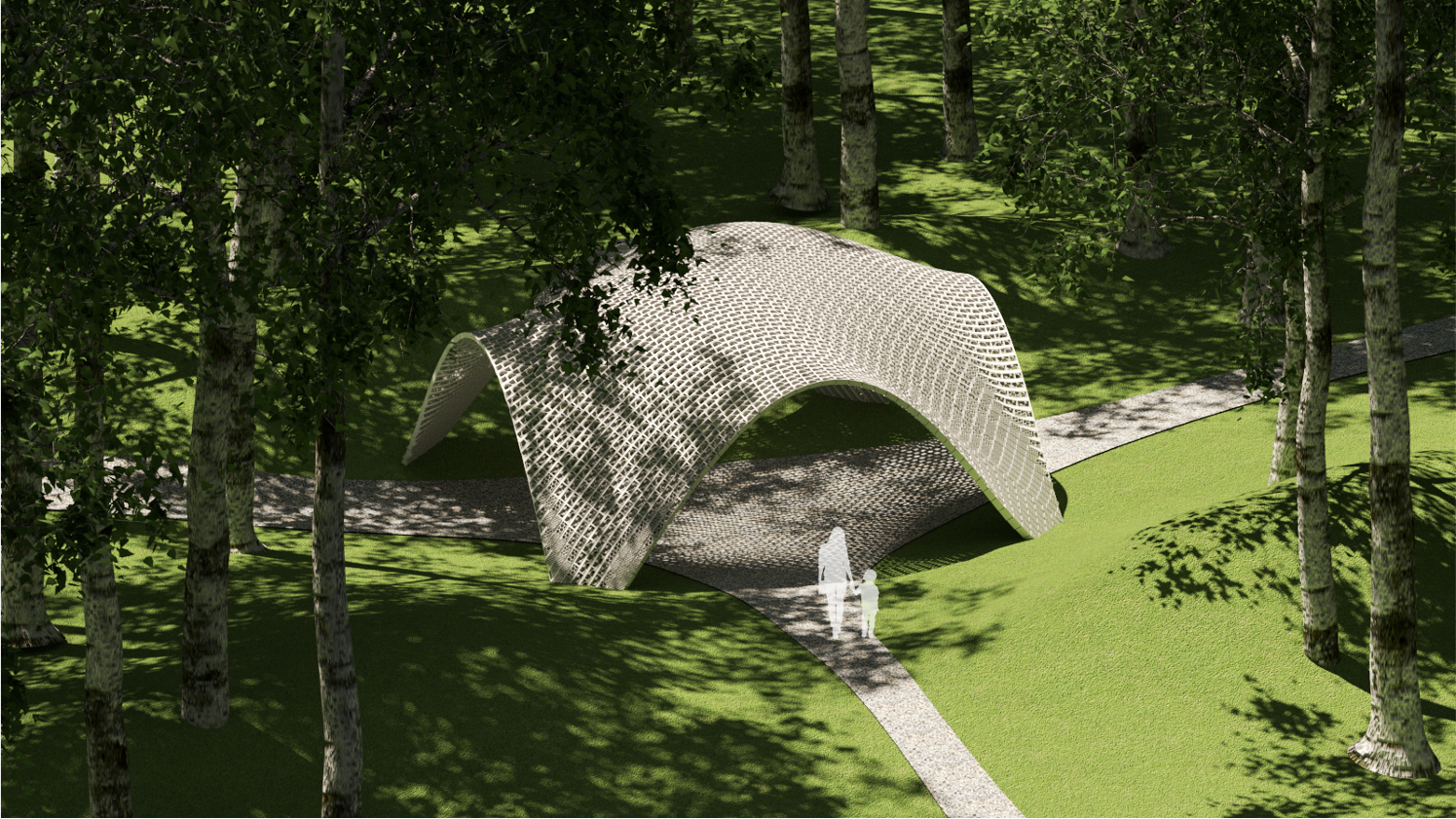
The pavilion site was a park. It provides a space for visitors to stop and rest. The shadows cast by the trees and the pavilion interact well with one another.
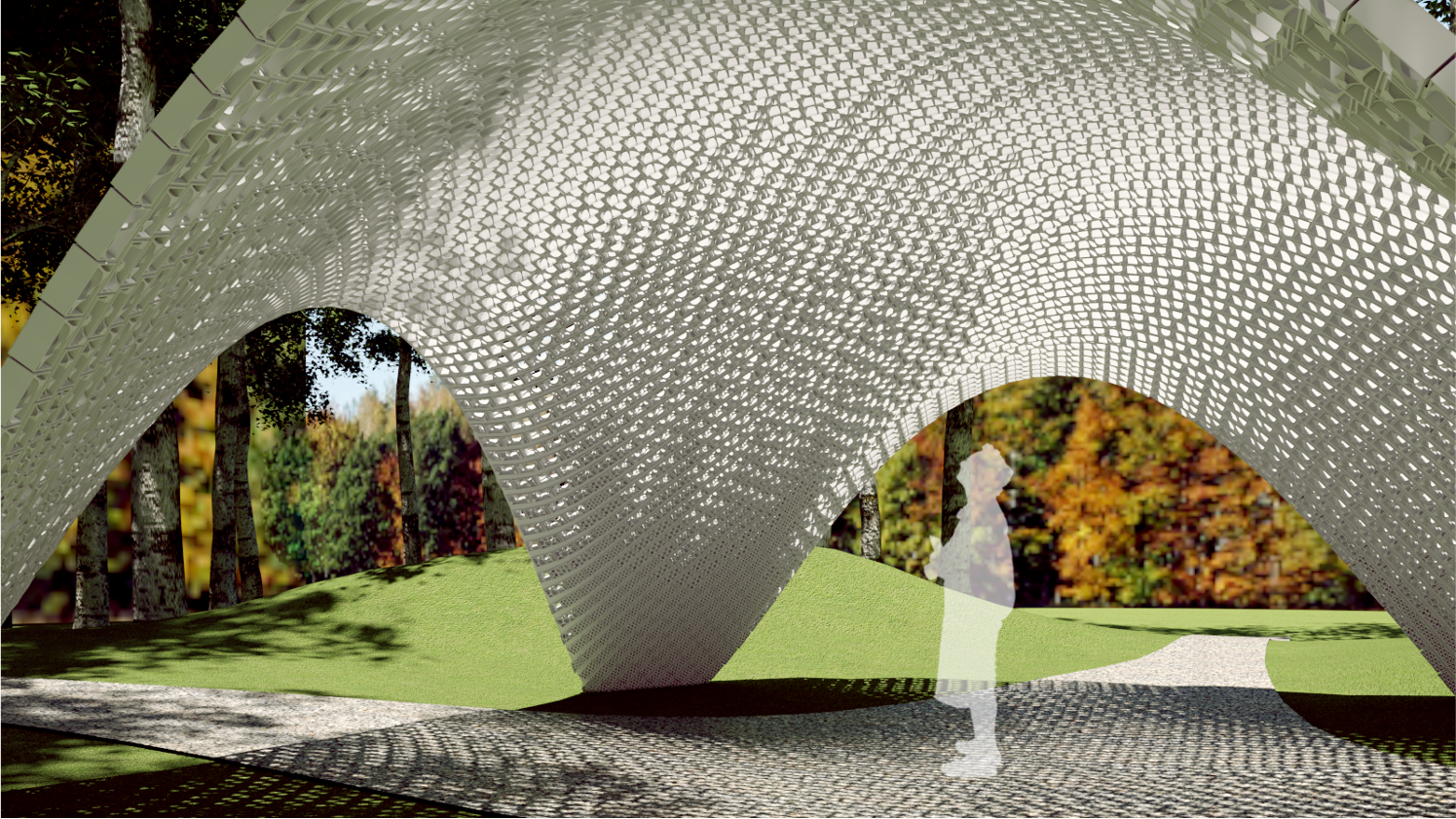
The lighting pattern on the underside of the shell shows the structural density.

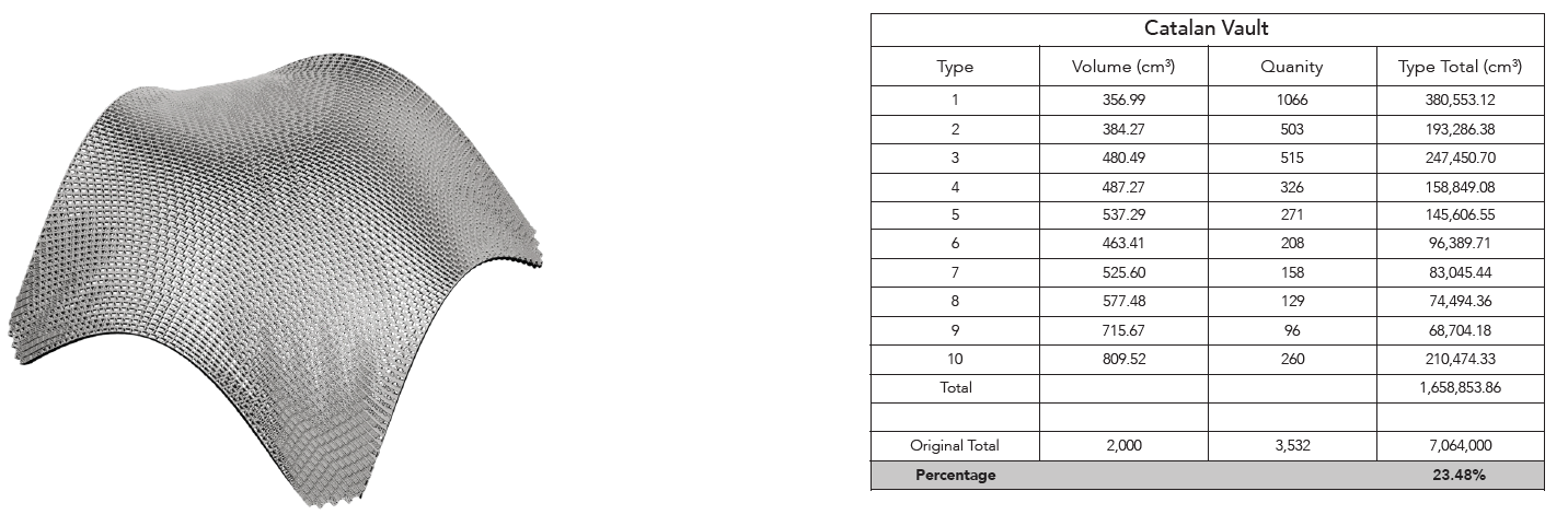
The structure was only 24% the volume of the structure with traditional blocks.
FABRICATION TESTS
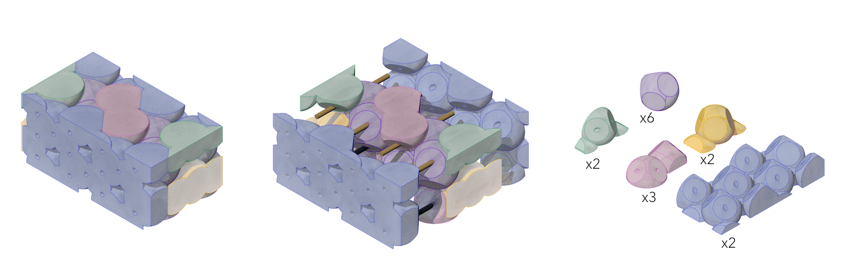
A new fabrication method was developed for this project since a small desktop 3D printer was being used for the project since a small desktop 3D printer was being used for the project with a 16 x 16 centimeter boundary. This method allowed for the creation of multiple parts that could be held together with wooden dowels. This new strategy eliminated the material bridging and need for support structures as a result of where the components were cut. This allowed for the block's volume to increase since the entire block was not being printed at once. The volume of the second block was 20 cm (L) x 10 cm (W) x 10 cm (H).
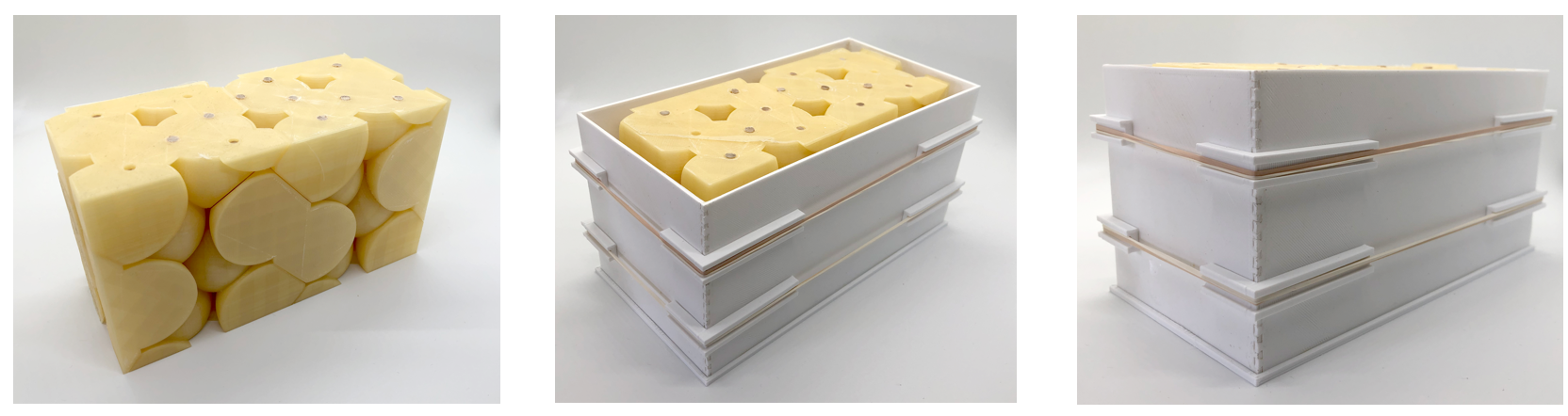
The photo at left shows the PVA formwork held together with the wooden dowels. The photos in the middle and at right show an additional formwork that was created using polylactic acid (PLA) filament. This formwork was used to create the boundary of Rockite that frames the interior apertures. This formwork was designed to be reusable.

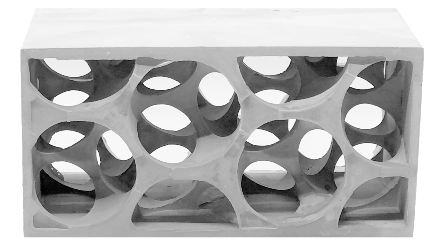
This was the block that resulted from the formwork.
A second formwork was fabricated for the second block.
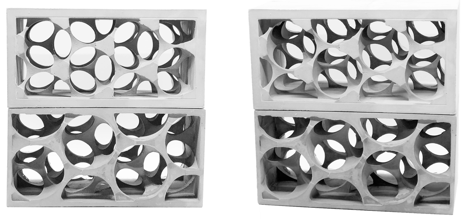
In this image the two final fabricated blocks were stacked to show the possible variation in porosity.