
Collaboration with Joonheang Lee
Professors: Chuck Hoberman
Teaching Fellow: Dan Tish
SCI 6478 | Informal Robotics
Harvard Graduate School of Design | Spring 2020
The objective of this project was to create a simple, easy to fabricate, steerable, walking robot using two degrees of freedom by use of parallelograms. The final robot was named the Double Parallelogram Walker due to its used of these mechanisms in its design. The robot is fully untethered and controlled by an infrared remote controller. It has been programmed to have four functions. These include forward and backward motion, rotating, and stopping. The Double Parallelogram Walker can be compacted into a flat pack that is six times smaller than when it is expanded. As a result, this design could allow for lightweight, compact transport. This robot is composed mainly of paper and three 3D printed components using double-sided tape as a binding agent. These three main materials totaling one dollar fifty cents with the bulk of the cost being the required electronics. This low cost and straightforward design could have many potential applications.
This is a video of our final robot. It is fully untethered and controlled by an infrared remote controller. It has been programmed to have four functions. These include forward and backward motion, rotating, and stopping. (Video is 8x Faster)
FORWARD MOTION
The following GIFs and images will document the iterative process in our search for a design utilizing parallelograms which would allow for forward motion.
The first exploration used two vertically extruded parallelograms attached at one face. This central surface remained rigid while the other three edges of each parallelogram actuated forward and backward.

The second design used two parallelograms attached at one edge. This allowed the parallelograms to be move vertically.

Legs were added to the middle and outer edges. The dimensions of the central and outer legs were different. The outer legs were longer to allow the center to lift upward when the outer legs were touching the ground.
A linear actuator in the form of a central tab was designed to allow for the expansion and contraction of the base length of triangle.
The movement of this central mechanism allows the outer legs to raise off the ground.

A tent was added so the wings would be actuated simultaneously.
A tent was added so the wings would be actuated simultaneously.

A tent was added so the wings would be actuated simultaneously.
DESIGN REFINEMENT
This section will document how this design moved from a hand actuated to an untethered, remote controlled robot.
A servo motor was added to the center of the robot. Initially the connection was through the front of the wing. This was quickly moved to the side making it perpendicular to the center of the robot. This design change allowed for less bending of the wings and a cleaner aesthetic. The wing was connected to the servo motor arm with a wire.
The central mechanism was altered to make actuation with a servo motor simpler.
For the first iteration for the new mechanism the servo arm was attached to the central parallelogram with string. This resulted in inaccuracies since there was a six-millimeter gap between the arm and the edge of the parallelogram. Meaning the motor’s rotational vertex was off center and did not allow for reliable movement. This was our final model that was fabricated using a laser cutter.
Using a new double parallelogram logic for the central mechanism we were able to get the robot to slightly lift off the ground at its center.
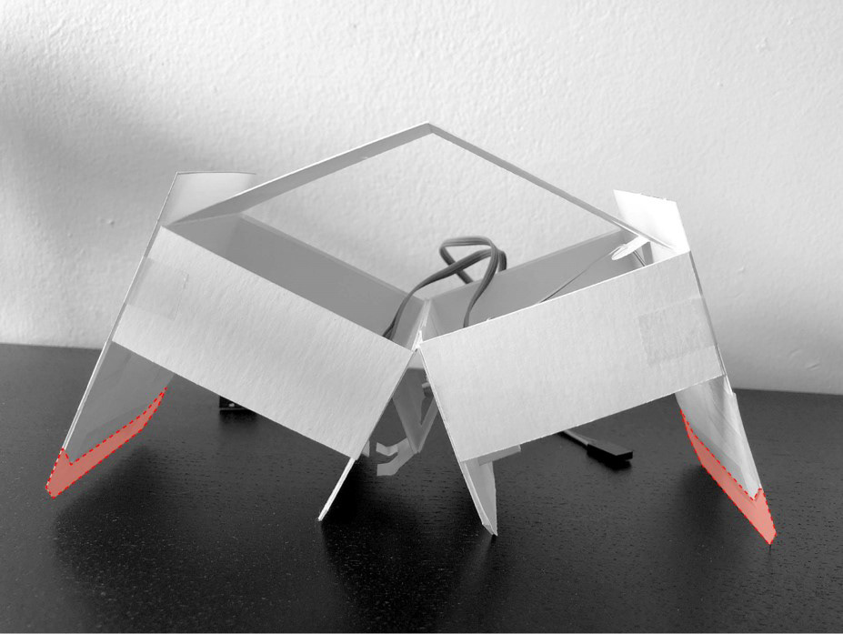
The outer legs of the robot were extended by half an inch with a sheet of paper on either side to increase the lift of the central legs. This allowed for a greater vertical lift of the central mechanism.
The alterations of the outer leg length allowed for sufficient vertical lift that the robot was able to take its first steps forward.
These first steps allowed for the realization that the robot had an uneven weight distribution due to the placement of the motors not being centralized. This caused the robot to often fall backwards. As a result, the servomotors were placed in the center rectifying the issue.
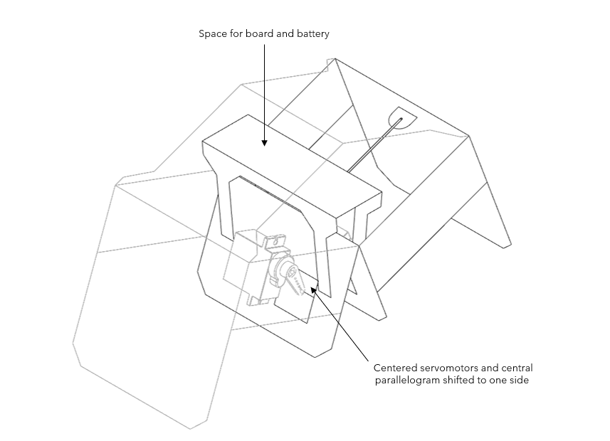
There was a platform added above the central mechanism to allow space for the Arduino board and battery.
Quickly we noticed that the platform had issues with lateral motion. This motion was concerning since it could allow for uneven weight distribution. This was resolved using a 3D printed platform in conjunction with the paper platform. This 3D print was designed to have a slot for a wire slider in each leg allow to allow the platform to move vertically as the central mechanism opened and closed. It has additional openings on the platform allowing for the pins of the Arduino board to pass though.
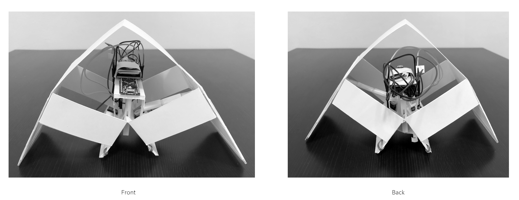
All electronic devices are placed on the 3D printed platform, this includes the Arduino Every, a lithium battery, soldered wires, and the infrared receiver.
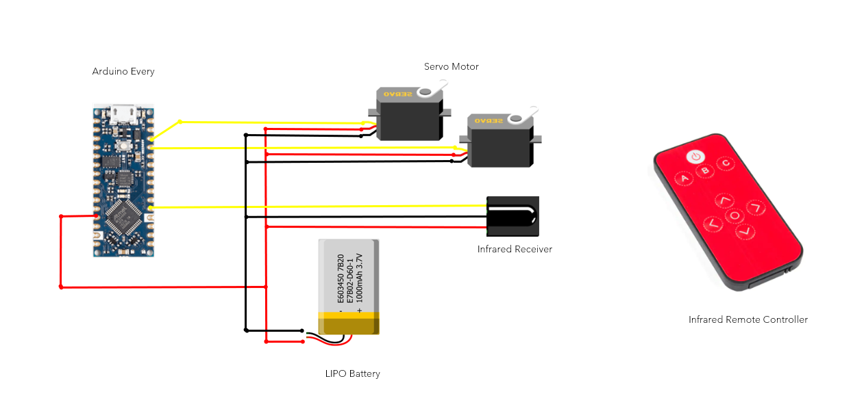
This diagram depicts all the electronic components used for this device. These electronics are powered by one lithium battery and controlled by an infrared remote controller.

The Double Parallelogram Walker was mainly composed of paper, but with the addition of the 3D printed platform it was decided that it would be helpful to 3D print the links between the servo motors. Prior to the 3D printed iteration, we had solely used wire for these connections. The wire tended to bend or shift whereas the 3D printed parts provided a more consistent connection.
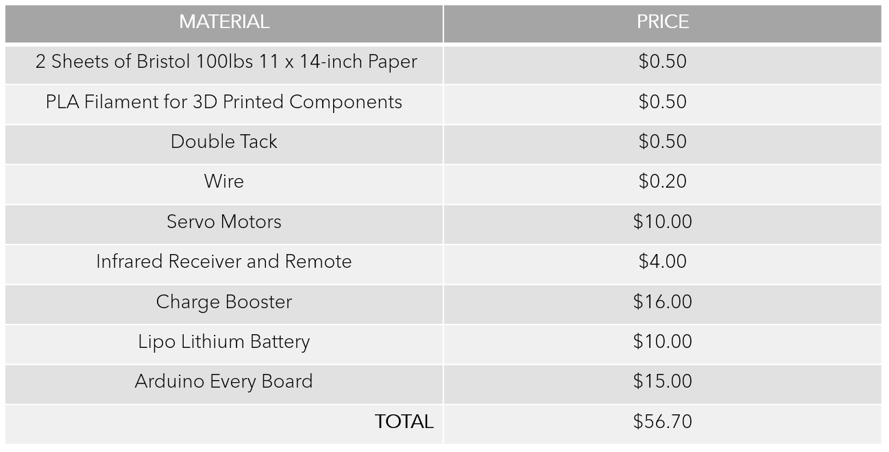
The total cost of the robot was approximately fifty-six dollars seventy cents. The fabrication components were quite cheap at one dollar forty-five cents with the bulk of the cost being the electronics.
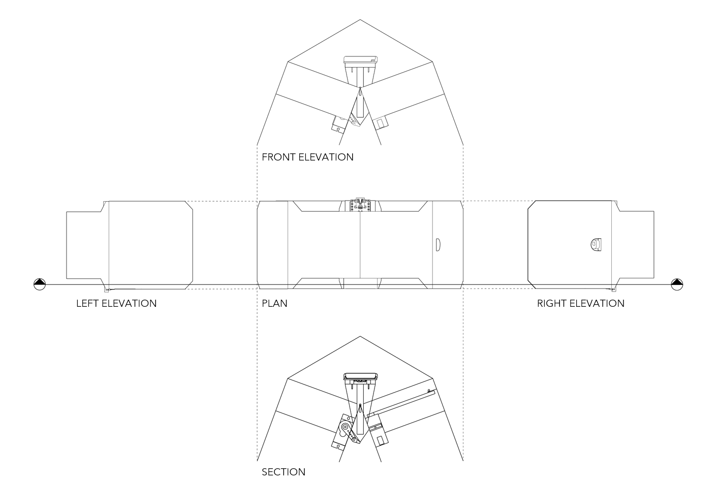
These orthographic drawings highlight the simplicity of the robot’s design.

The Double Parallelogram Walker was able to be fabricated using two sheets of 100lbs 11 by 14-inch paper.
Physical Adjustments and Programmed Control
The following section will discuss how steering control was developed. Two methods were used in attempting to control the steering of the robot. The first was adjusting the slope and length of the wing. The second was by controlling different combinations of movement via programming.
This video documents that the robot naturally turns to the right.
This slide documents the relationship between the wing conditions and steering. Instead of fabricating a new robot, additional layers of paper were applied using masking tape to the outer legs with varying edge conditions. The four videos document how these alterations impacted the steering.
Using the information obtained above the robot was able to be programmed to move forward. This motion was achieved by placing a sloped edge condition on the left outer leg. (Video is 8x Faster)
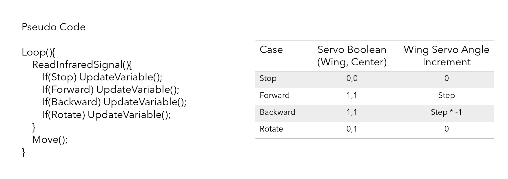
Rather than using a physical alteration to the robot's outer legs to gain control of steering it was decided to lean into the natural movement to the robot to its right. As a result, four types of movement were created. These movements included stop, forward, backward, and rotate. The forward and backward motion toggled between a positive and negative rotation step of the servo motor controlling the wings. The rotate or turning motion was controlled by solely actuating the central servomotor which allows the robot to pivot.
In this video the remote was used to move the robot 180 degrees. (Video is 8x Faster)
In this video the remote is used to move the robot forward 2 steps, backward 3 steps, and forward 1 step. (Video is 8x Faster)
This video documents the capabilities of the remote-controlled movements. (Video is 8x Faster)
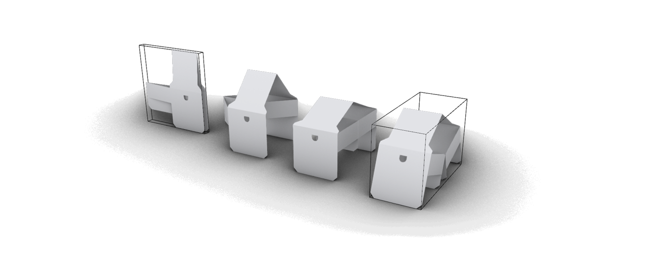
This robot can be compacted into a flat pack that is six times smaller than when it is expanded.