
Collaboration with Haley Arthur Eisenmann
This project combines 3D printing and conventional hand-building of unfired clay to leverage each strength in creating custom, zero-waste, reusable formwork. The fabrication method relies on the plasticity and water-solubility of clay in an unfired state to permit the production of larger, more complex clay formwork. This is achieved through the aggregation of 3D-printed units with hand joinery. Since unfired clay possesses limited strength and struggles to hold its weight, shredded paper was introduced. The research first explores the compressive strength of clay with various ratios of added paper. The process of creating paper clay is explained, and its ratios are documented. Next, fabrication case studies at multiple scales are introduced to explore paper clay’s viability as a formwork. The paper clay self-demolds as it dries, shrinks, and falls off the concrete form. This allowed all the clay to be conserved. All the clay from the test was rehydrated and recycled to be reused. The fabrication tests demonstrated the effectiveness of the fabrication workflow. The results point to future research that may reduce the embodied carbon emissions of concrete casting through formwork recycling.
This project introduces a way to combine 3D printing and conventional hand-joining methods to create larger and more complex formwork. Additionally, it explores the integration of shredded paper to increase the clay’s strength while reducing its weight. This process is documented through a series of compression tests to ascertain the most robust ratio of clay to paper. Next, fabrication case studies at multiple scales are introduced to gauge the viability of the fabrication method.
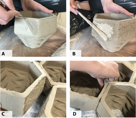
Above Images: Unit Joinery (A) scratching of the lower half, (B) applying the liquid clay to the surface, (C) aligning the correct sides, (D) applying pressure to weld units.
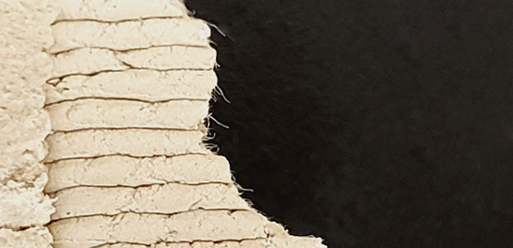
The image above shows the paper fibers within the clay.
The first test used a set of units measuring 25.4 mm x 25.4 mm x 50.8 mm. The design utilized hexagonal tiling. Each unit had a top and bottom half of the geometry, each with a distinct role. The bottom allowed the units to be joined and
aggregated into the desired formwork. The top of each unit held the casting material. The units were printed using a single spiralized curve. These units were printed using a 2 mm diameter nozzle.
The 17 units were tessellated into an arch using hexagonal prisms. The units were joined using traditional ceramic methods. The bottom faces of the units were scratched or scored using a feather wire tool for clay sculpting. Then, a medium paintbrush applied porcelain slip or liquified clay to the surface. The slip acts as an adhesive. Slip is created by adding water to clay in a container and mixing it with an immersion blender until a thick liquid is formed. The units were then pressed together by hand to create the formwork. All the edges of the formwork were then patched with flat slabs of clay. It was discovered that the bottom portion of the formwork could be shorter, allowing for less material and printing times to be expedited.
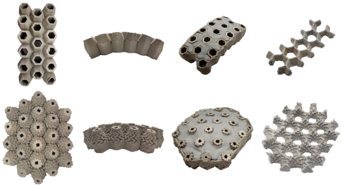
The above images show top and side formwork, cast formwork, and the resulting cast for iterations 1 (top) and 2 (bottom).
The second iteration tested the possibility of applying custom patterning through toolpath manipulation on the top of the unit (Figure 3). A zig-zag pattern was applied to utilize a series of clay overhangs. The unit’s texture was explored through 3D printed tests to find the best overhang distance for the loops to provide the greatest texture (Figure 4). The texturing proved successful and created a unique texture on the cast. It was noted in this iteration that using one regular hexagon unit resulted in gaps between units as they were assembled further away from the center. Thus, multiple unit types would be needed to create a geodesic dome.
The images above show the unit texture test (top) and the second iteration (bottom).
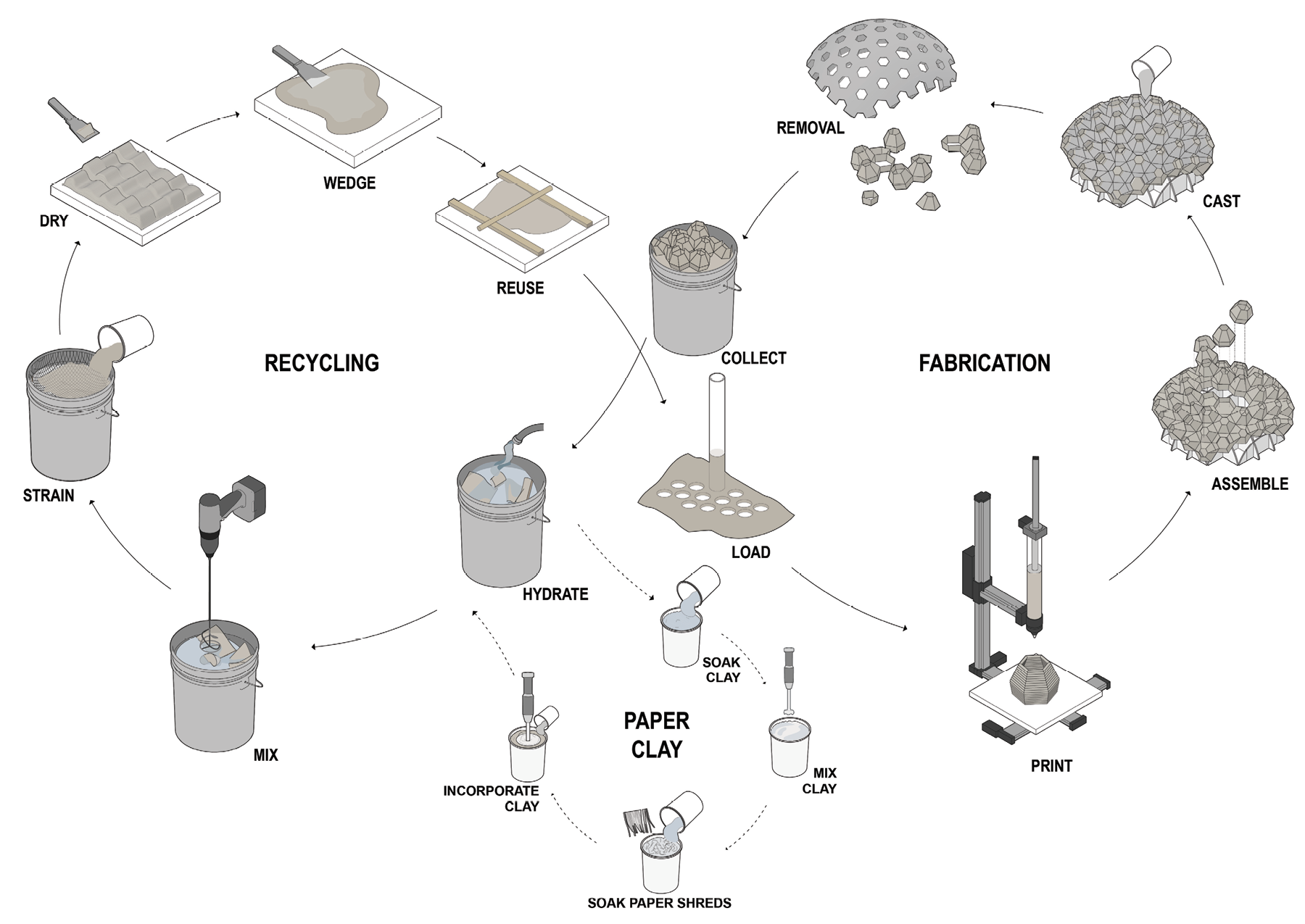
The clay formwork was conserved for reuse. Water was added to the dried clay to create a liquid. The liquid clay was strained to remove unwanted casting material or foreign objects. The clay was dried on plaster slabs to decrease its moisture for approximately 5 hours. This process allowed it to return to the desired viscosity required for 3D printing. Once the clay is removed from the plaster, it is worked by hand or wedged before its placement in a sealed container to remove air and inhibit further desiccation.
Diagram above: (0) Creating paper and clay mixture 1-2 hours, (1) letting the clay dry on plaster 12–24 hours, (2) printing units 15 minutes per unit, (3) Assembling formwork 1-2 hours, (4) Casting 1 hour, and (5) Removing clay and soaking in water 10–12 hours.
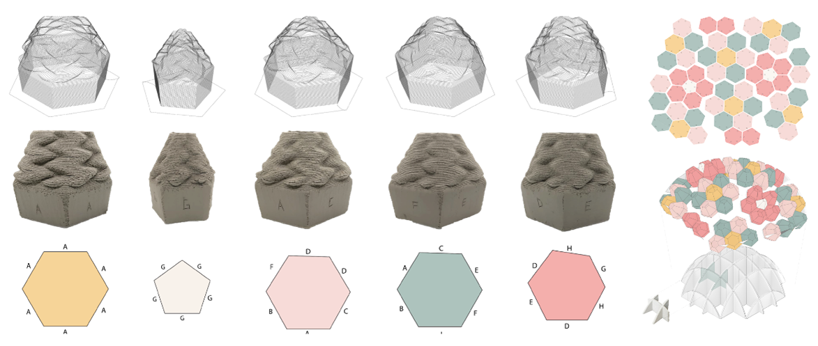
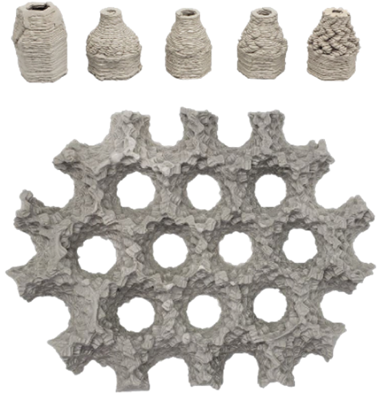
The next test increased the scale of the units (approximately 16 cm x 14 cm x 12 cm), resulting in a 1-meter dome. This design used five base shapes: four hexagonal and one pentagonal. The layout, assembly, and structure of five final unit designs, with a 3D printed formwork callout, are depicted in the diagram above. The top of each unit varied in aperture size and pattern. Fifty-two units were printed in total. These units used a nozzle (6 mm) 3 times larger than the prior iterations. This allowed for a larger bead width for the single spiralized print, creating a stronger unit.
Since the units were printed individually, the limitations of the print’s volume and the size of the tube were not a hindrance.
To prevent the units from drying, while others were 3D printed, each was wrapped in plastic and stored in a container. This was important because the casts needed to remain in the leather hard or partially dry state. This is the most robust state before firing clay. If the clay were to desiccate to a bone-dry (dehydrated) state, it would absorb too much of the casting material’s water, weakening the formwork and resulting in a failed cast.
This iteration was the only one to require a substructure to construct the formwork. This, too, could be recycled and reused.
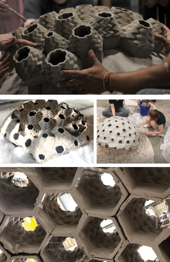
The images above show the assembly (top), formwork before casting (center left), removal of formwork (center right), and clay formwork before removal (bottom).
The substructure was subdivided using the clay printer’s bounding box and printed in paper clay. Therefore, it, too, could be recycled and reused. This iteration was the only one to require a substructure to construct the formwork. This substructure was subdivided using the clay printer’s bounding box and printed in paper clay. Therefore, it, too, could be recycled and reused.
The units were first joined into small groups of 5 to 6 before being fully assembled. The assembly took under an hour with a 4-person team. In conjunction with the formwork, the compressive strength of the paper clay subframe supported the casting material.
The more sloped areas of the clay formwork needed to be patched with a layer of clay to hold the casting material. The casting required several layers of material with varying viscosities and multiple rotations to fill the formwork consistently. The clay formwork was allowed to dry, which resulted in it shrinking and falling off the cast. The resulting cast was successful.
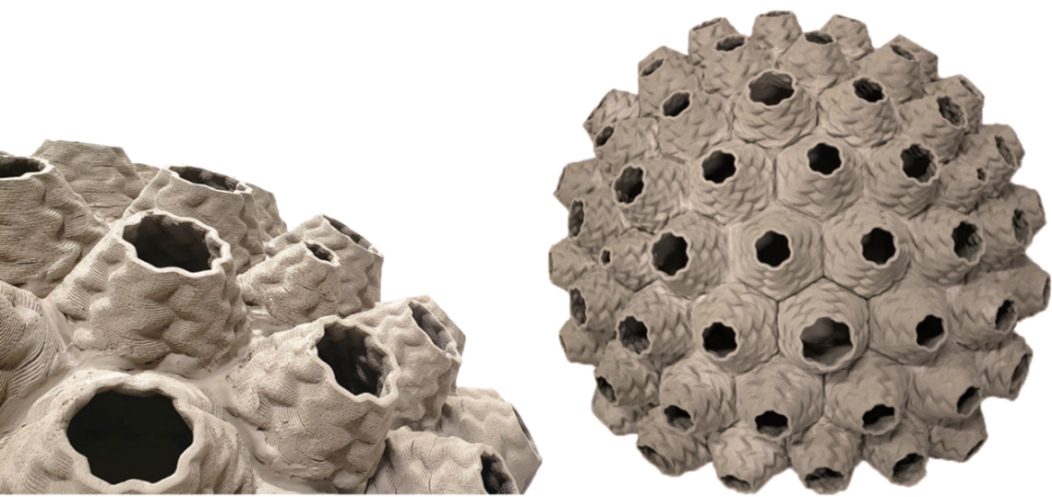
Images of the composite clay formwork before casting.
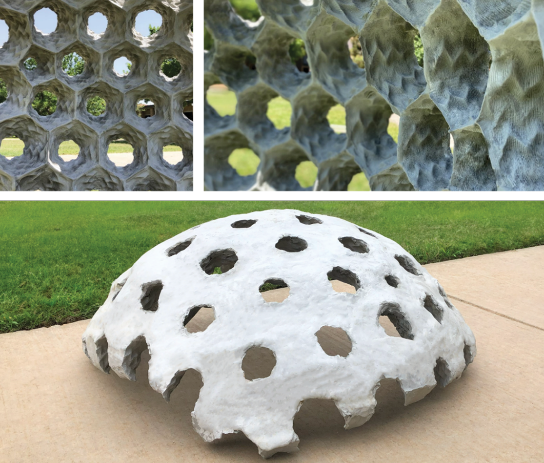
Images of the final vault