Collaboration with Molly Mason
Professors: Jose Luis Garcia del Castillo Lopez and Zach Seibold
SCI 6365 | Enactive Design | Final Project
Harvard Graduate School of Design | Spring 2020
This project seeks to develop a dialogue between humans and machines where machines aid in the creative exploration of fabrication processes and authorship is challenged through a collaborative design process between human and machine. It was inspired by precedents like Sol Lewitt’s Wall Drawings which possess similar themes of interaction and indeterminacy. A Wall Drawing consists of a set of rule-based procedural logics to be executed by different individuals in different locations. The results are unique creations in which the materialization design is challenged to adapt to the environment and the judgement of the draftsman. The work challenges the traditional importance of the hand of the artist by focusing instead on the dynamic relationship between artist, the executor, and the design of the system itself.
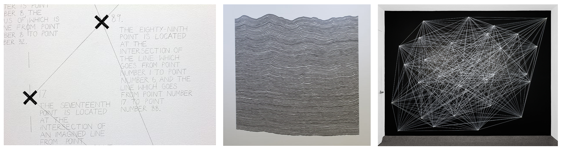
Wall Drawing 305 (1977), Wall Drawing 869 (1998), Wall Drawing 815 (1997), Sol Lewitt
The aim was to develop relationships between humans, machines, and physical making in which designs can be collaboratively generated and produced through turn-taking or real-time interaction. This collaboration can happen in multiple manners: the machine can be a medium for the collaboration between two remote humans in quarantine, for example. Design can be co-generated by machine translations of human movement or human adjustments of machine movement. The canvas becomes an opportunity for a sequence of generation and reflection in which drawings could have the opportunity to interact with themselves, by adjusting what is drawn to what is already there.
The initial intention was to create a framework for interactive robotic ceramic 3D printing to allow for changes in extrusion rates, travel speed, layer heights, and form via hand gestures while the print was in progress. This would allow the user to adjust parameters mid print based on observed data during the fabrication process. The design of prints could then be a collaborative process between human and machine where the robot is not simply delegated a task but used as a tool for design exploration.
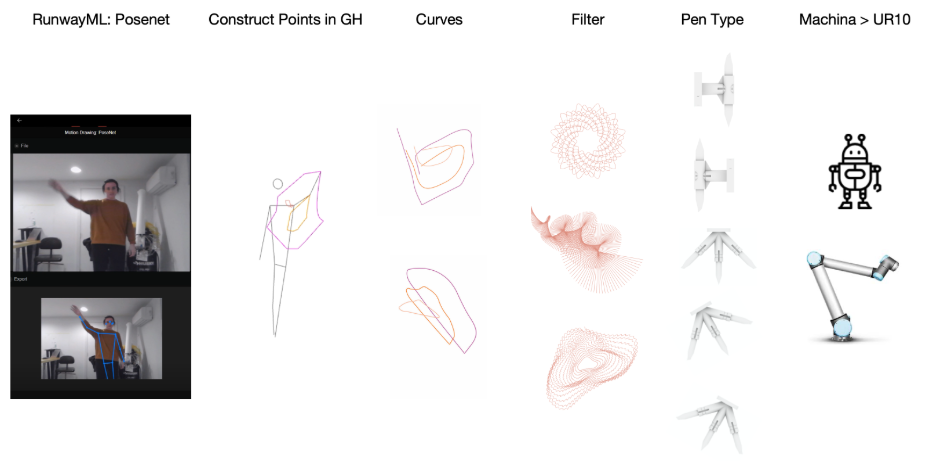
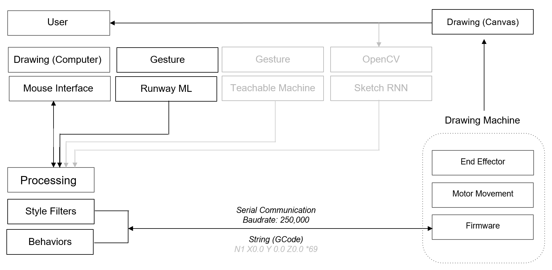
The initial workflow used for the robotic drawing assignment was linear. The curves were created via the user by tracking the movement of the wrist, elbow, and shoulder using RunwayML’s PoseNet. The coordinates of these locations were brought into Grasshopper as points to create three interpolated curves. The curves were then transformed using various Grasshopper filters. These paths were then sent to the UR10 using Machina. The curves were plotted by the UR10 using a variety of custom toolheads. The combination of geometrical filters and different shaped drawing tools resulted in unique fabrications, much like Lewitt’s Wall Drawings. The same set of gestures could be used to layer different filter translations onto the same canvas. These results are interesting to us because gestures are used to generate design but the output is not a one-to-one translation. This provides the opportunity for qualities to emerge that were not apparent at the beginning, allowing you to design and fabricate in new ways.
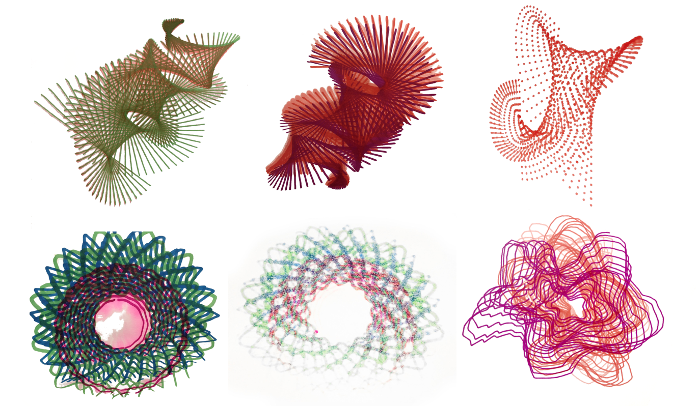
Given current events, we were unable to pursue our original intention of working with ceramics. We instead chose to focus on some of the drawing results we found interesting which were the qualities of drawing that only become evident in their materialization: conditions like bleeding, build up, overlapping, smearing, and selective line plotting which are results of the geometric pattern, timing, end effector orientation, and material, in this case, ink. We were interested in developing a way of making where we could exploit these qualities without restarting and executing pre-conceived drawings by exploiting a cyclical workflow in place of a linear one.
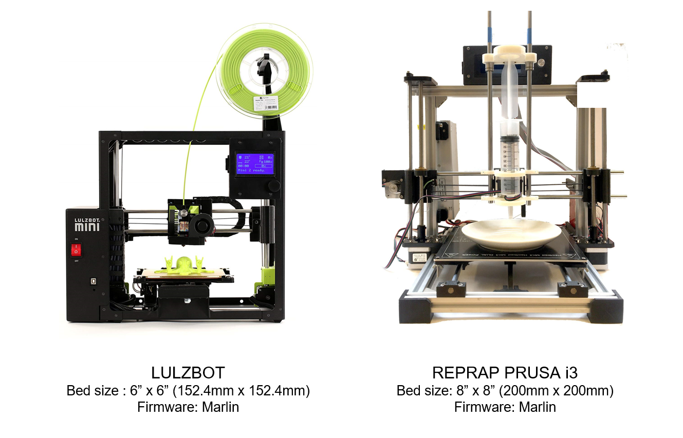
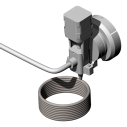
Our new agenda required the hacking of two desktop 3D printers by removing their extruder carriages and attaching a custom pen holder.
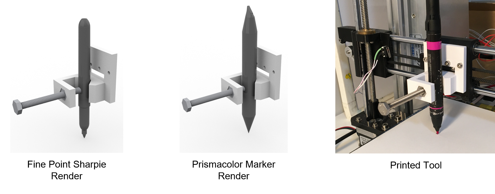
A custom end-effector was designed to attach to each 3D printer. These allowed for the use of a variety of cylindrical tools without having to reprint or design an additional part. A Grasshopper definition was developed allowing for the capability to alter, scale, and reprint rapidly.
WORKFLOW 01 | OCTOPRINT
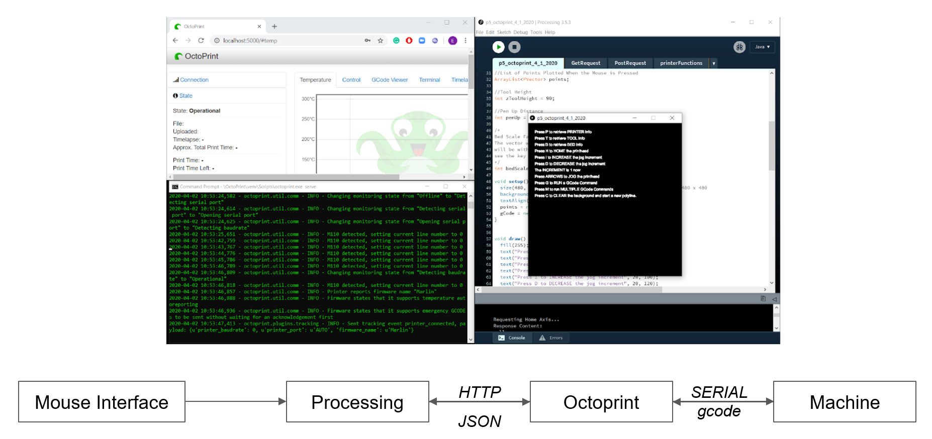
We first had to establish a connection between our printers and computers. This workflow utilized a third party software called Octoprint as a middleman between Processing and the 3D printer. Processing sends commands to an Octoprint server through JSON requests. Octoprint then relays these directions to the 3D printer.
To use this workflow one needed to have the processing window, its canvas, their command prompt, and Octoprint open to send the commands to the 3D printer. Various tasks were sent to the printer by pressing certain keys on the keyboard. Pressing the arrows allowed the user to jog the printer, pressing H homed the printer in all three axes, and pressing M allowed multiple GCode commands to be sent to the 3D printer.
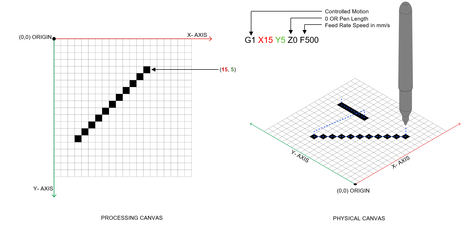
When the mouse is pressed on the Processing canvas the X and Y coordinates are saved to a list. When the mouse has been released this list of coordinates is used to create a series of new vectors. These vectors are converted into GCode format using a for loop that iterates through the list of points appending the list. Within the string formatting, these vectors are scaled to fit inside the 3D printer’s bed boundary. This list of GCode commands is sent to the printer using a JSON object which allows the sending of multiple GCode Commands.
Translation from Processing Canvas to physical canvas, included a scaling operation and physical constraints like a pen up function. The pen up function consisted of two additional GCode commands that were added to the list which allowed for the first and final coordinate to be raised by a set increment. This allowed the pen to lift off the page at the beginning and end of each line so that the travel from one polyline to another was not plotted.
For these iterations the drawings were replicas of the polylines drawn in Processing canvas. This one to one process did not allow for any diversion from the users drawing to the output.
Interest was developed in the process of turn-taking where the user draws a line, sees it materialize through the machine, and is able to adjust future decisions thus creating an exchange of ideas between human and machine. This sequential operation could allow the drawing to interact with itself in ways such as avoiding existing lines or changing colors. These iterations failed to require the use of a 3D printer’s precision since the results were as imprecise as the hand drawing itself. Moving forward it was determined to leverage the capabilities of the 3D printer.
WORKFLOW 02 | SERIAL COMMUNICATION
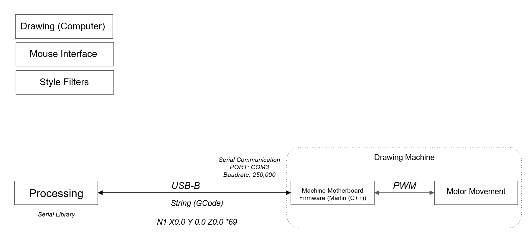
To take advantage of the data provided by the printer, we had to establish a more direct connection in which we could have better control over what we were sending to the printer and what information we were receiving without having to use a middleman such as Octoprint. We therefore came to know the firmware, Marlin, installed on our printers. Communicating with this firmware is key as it translates GCode into motor movement. We had to develop a way of speaking the right language. This also gave us the opportunity to incorporate our filtering process from earlier studies.
Filters were added to the workflow in an effort to exploit the 3D printer’s precision. Additionally the filters allowed for the manipulation of the polyline creating a difference in the output of the hand drawing and that of the 3D printer. This process increased the user’s anticipation in discovering the 3D printer’s final output. One could choose between three filters or the original polyline. Each filter had additional parameters that could be modified.
This filter allowed the polyline to be broken into a series of dashes. The length of the dash could be changed by the user.
The second filter turned the polyline into a spiral. The user could increase or decrease the radius of the spiral as well as decide if the radius would remain consistent or incrementally change.
The third filter turned the polyline into a zig-zag. The user could vary its amplitude. If the inputted polyline was drawn on the Processing canvas slowly, the zig-zag was more dense the inverse was also true since the speed of the cursor determined the number of points plotted on the canvas.
By using the take over screen share feature of zoom, the machine can be used to mediate collaborative drawings despite remote locations such as drawing done by a child. This differs from something like a typical printer in that lines are drawn procedurally, allowing for real time adjustments. The filtering techniques are further differentiated by how quickly a line is drawn - as evidenced here by the dotted lines on the left and the zig-zag lines that come to register as a type of hatch. This combination of motion and speed begins to describe the gesture used to create it.
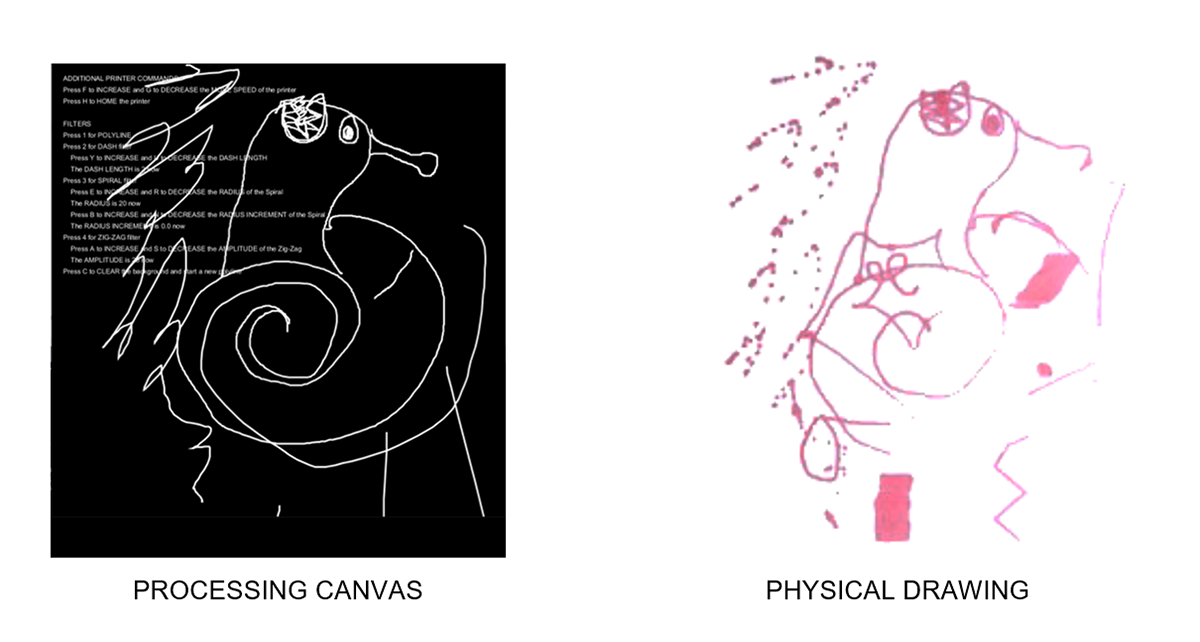
(Snail) So as you can see here the lines on the left materialize as dots with a differentiated frequency which reflects the speed at which points are collected (or how fast the lines were drawn)
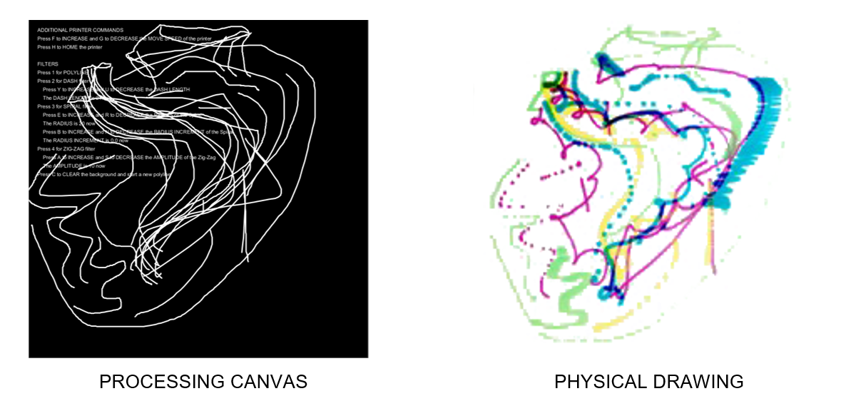
(Heart) This deviation between what is created by the human and what is created by the machine results in an explorative way of working where the human and machine participate in a dialogue to collaboratively author a drawing.
WORKFLOW 03 | GESTURE-BASED INTERFACE
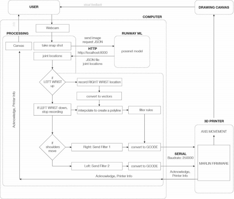
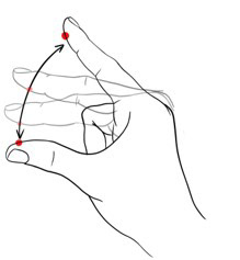
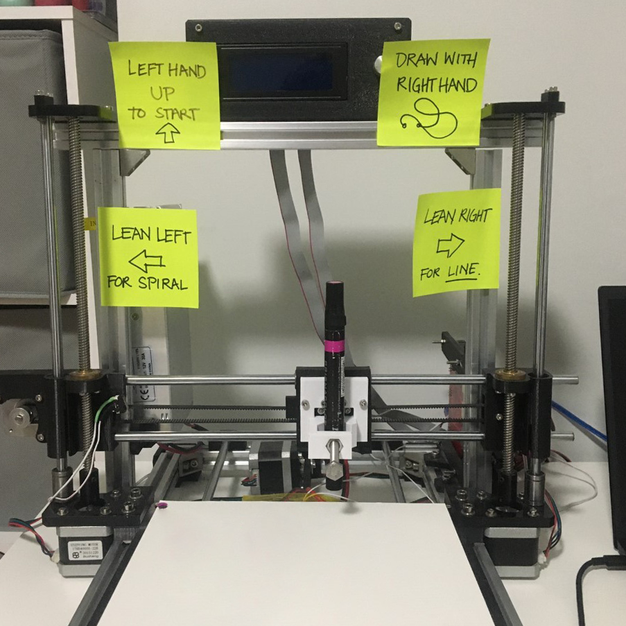
Our final workflow allows for a series of behaviors and filters to result in unexpected drawings, creating an exploratory collaboration tool. The Processing canvas provides the user with the commands needed to control the filters and their variables. Additional commands included changing the move speed, homing the printer and clearing the polylines. By raising one's left wrist above the center of the Processing canvas, the location of the right wrist begins to be recorded; these positions are converted to vectors and interpolated to create polylines. If the user’s right shoulder moves into the far left of the Processing canvas the polyline is sent to the printer and is plotted. The inverse is true for the left shoulder and the far right of the canvas only this time it plots a filter. Similar gesture logic could be added to increase the complexity of the system.
Our final set of experiments sought to re-incorporate gestures as an interface between the human and machine. The interface used a set of “intuitive” hand and body movements to record points and sent them to the machine.
To test the validity of this system, we invited one of our quarantined roommates to test the machine using gestures. Users did observe that for them what was most exciting was not what was happening on the computer but what was materializing on the canvas.
By establishing this connection and set of behavioral rules, we have contributed towards a framework which allows for a real-time, collaborative design exploration tool between humans and machines. In the future, we are interested in developing the framework to include material processes other than mark-marking, developing the interfaces between “hand” and machine, and developing machine personalities through additional forms of machine intelligence.